Buyer takeaway
Clarify the connector requirement
Compare product and solution paths
Prepare RFQ details before quotation
Interface definition
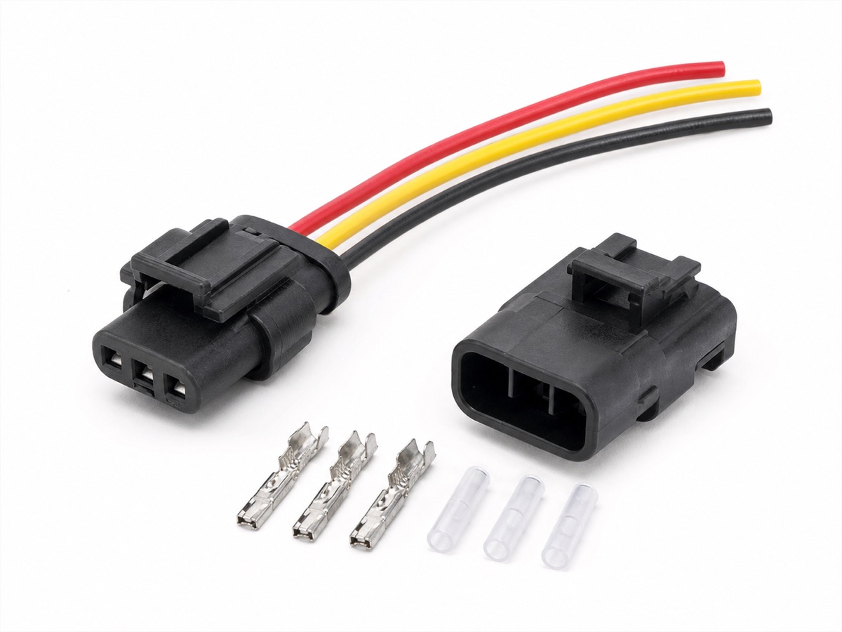
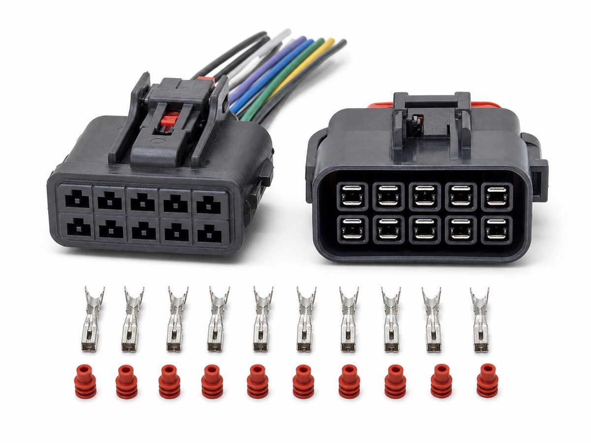
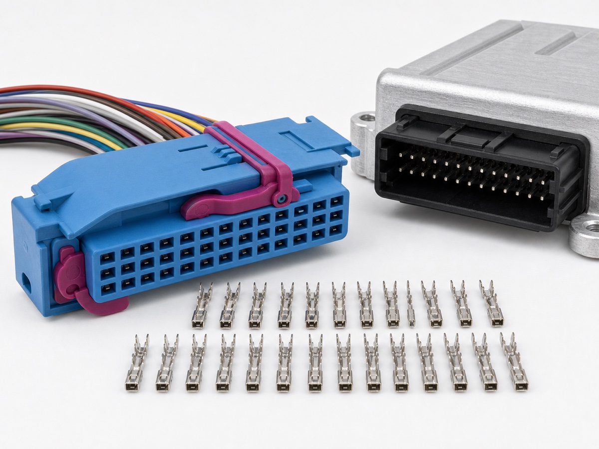
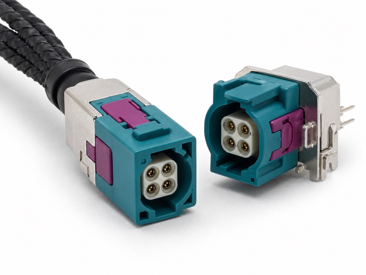
Wire-to-wire connectors join two harness sections. Wire-to-board connectors mate a harness-side plug with a PCB header or module interface. Similar cavity counts do not make these interfaces interchangeable.
Wire-to-wire selection
Review harness routing, cable exit, mating frequency, sealing, terminal family and whether both plug and receptacle sides are needed. Inline connections should also remain accessible for assembly and service.
Wire-to-board selection
Confirm PCB header orientation, mounting style, pitch, keying, board layout, module enclosure and harness-side mating geometry. A module drawing is usually more useful than a housing photo alone.
Common sourcing mistake
Buyers sometimes submit only the harness-side connector. Without the mating header or interface drawing, latch direction, keying and terminal position can be misidentified.
RFQ information
State wire-to-wire or wire-to-board, provide both mating sides, pin map, wire range, current, sealing need, header orientation and sample quantity.
FAQ
Common questions
Common procurement and engineering questions related to this topic.
Can a wire-to-wire connector mate directly with a PCB?
Only when that connector family includes a compatible PCB header. The header drawing and orientation should be verified.
What is needed for a wire-to-board connector RFQ?
Provide the module or PCB header drawing, mating connector, orientation, pin map, electrical requirement and installation space.