Buyer takeaway
Clarify the connector requirement
Compare product and solution paths
Prepare RFQ details before quotation
Control both sides of the interface
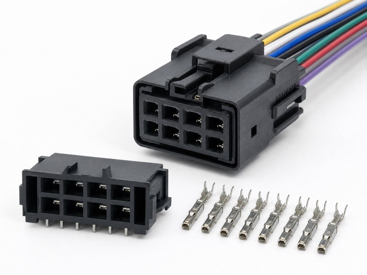
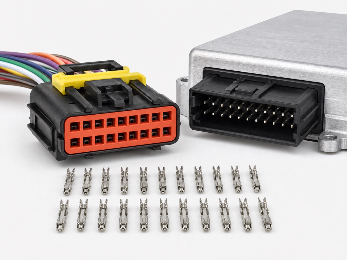
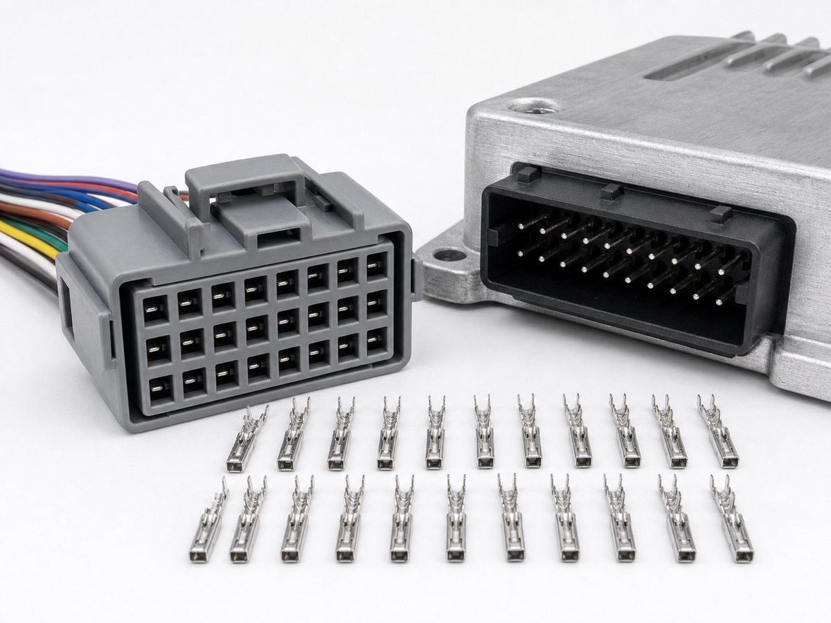
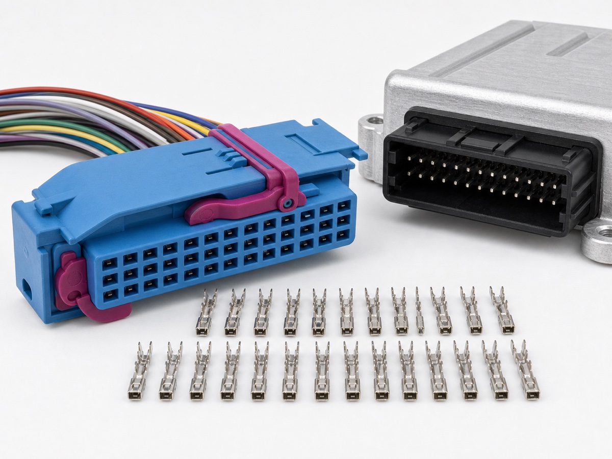
Treat the cable-side connector and PCB header as one interface. Confirm cavity count, keying, polarization, terminal family, mating direction, connector envelope and the controlled drawings for both sides.
Straight versus right-angle routing
A straight header can support vertical mating while a right-angle header can route the harness parallel to the board. The correct option depends on enclosure depth, side clearance, harness bend radius, access and assembly sequence.
PCB and enclosure constraints
Review footprint, through-hole or other mounting requirements, board thickness, keep-out area, retention features, sealing interface and tolerance stack. Check that the connector can be mated and latched after the module is installed.
Harness and service access
Plan cable exit, strain relief, bundle routing, latch access and removal tools. Avoid sharp bends immediately behind the connector or module features that prevent full latch engagement.
Drawing package for RFQ
Provide PCB layout constraints, header orientation, enclosure section, connector keep-out area, mating connector, pin map and expected assembly direction. A photo alone is not enough to control the board interface.
FAQ
Common questions
Common procurement and engineering questions related to this topic.
Can straight and right-angle headers use the same PCB footprint?
Do not assume so. Footprint, mounting, keep-out area, pin geometry and enclosure clearance must be confirmed from controlled drawings.
What is the main routing check for a PCB connector?
Confirm harness exit, bend radius, latch access, mating direction and enclosure clearance in the installed module condition.